
Audio Amplifier Circuit
In this tutorial, we are going to make a “Simple PAM8403 Audio Amplifier Circuit
PAM8403 is an Amplifier IC. This IC is a filterless binary – channel, 3W, class- D stereo Audio Amplifier, that offers low THD N which allows it to achieve high – quality sound reduplication from a stereo input and also provides an effectiveness of over to 90. It has a special point that is, it can drive speakers directly from its affair. It can give 3W affair with a 4Ω Loud Speaker and the Operating voltage for this IC range from 2.5 V to 5.5 V making it ideal for adding the audio capability to your MP3 and MP4 player systems. With a number of readily available external factors, a simple PAM8403 amplifier circuit can be designed.
Component List
🔧 The PAM8403 amplifier circuit is compact yet powerful, and it includes several key components that work together to deliver crisp stereo audio. Here’s a breakdown of the essentials:
To build an audio amplifier circuit, the following components are needed.
PAM8403
To explore the pin configuration, dimensions, and technical specifications of the PAM8403, refer to its official datasheet.
Audio Amplifier Circuit
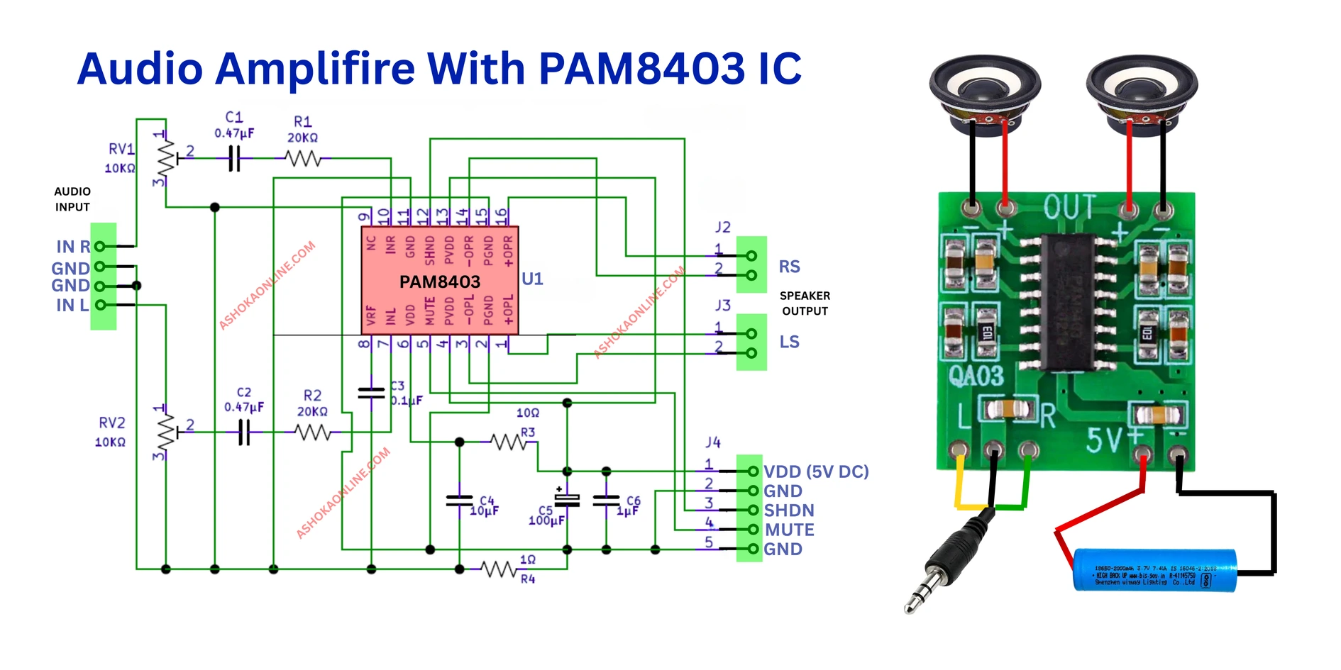
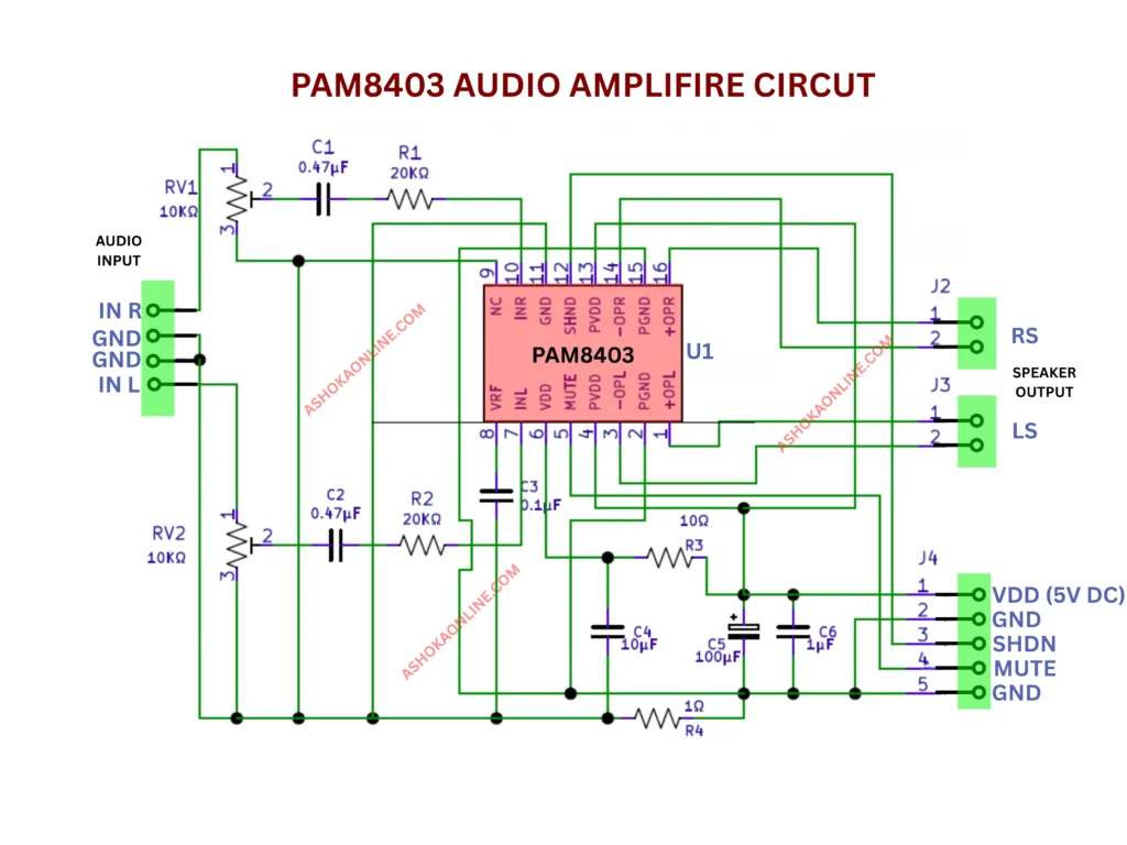
The PAM8403 is a compact audio amplifier IC that comes in an SOP-16 package. It features a modern filterless design, allowing it to drive speakers directly without the need for low-pass output filters. To ensure safe operation, the IC includes built-in short-circuit protection, which is essential in any audio amplifier system.
In this particular circuit, power is supplied to both the Analog VDD and Power VDD through the J4 connector, along with the Analog GND and Power GND. The J1 connector serves as the audio input terminal, where the INL and INR pins accept the left and right channel audio signals from a stereo source. These signals are routed through variable resistors and capacitor filters before reaching the IC.
Ceramic capacitors rated at 0.47µF are used to suppress power supply noise that may interfere with the output signal. The processed audio signals are then output to the right and left loudspeakers via the J2 and J3 connectors, respectively. By adjusting RV1 and RV2, users can control the volume of each channel. Additionally, the Mute and Shutdown (SHDN) pins are active-low, meaning that applying a ground signal to these pins will mute or disable the amplifier.
Applications
- Suitable for use with portable speakers, DVD players, and gaming devices.
- It can also be integrated into any amplifier project that requires a compact design and operates on a 5V power supply.

Boat stone 850 motherboard circuit board all projects and details